

How To Many Bits Doe Registers Hold In Armsim
ARM uses a load-store model for memory access which means that only load/store (LDR and STR) instructions can access memory. While on x86 most instructions are allowed to directly operate on data in memory, on ARM data must exist moved from memory into registers before being operated on. This means that incrementing a 32-bit value at a detail retentiveness address on ARM would require three types of instructions (load, increase, and store) to first load the value at a item address into a annals, increment it inside the annals, and store it dorsum to the memory from the register.
To explain the fundamentals of Load and Shop operations on ARM, we start with a bones case and go on with three basic offset forms with three unlike accost modes for each offset form. For each example nosotros will use the same piece of assembly code with a different LDR/STR offset course, to go on it simple. The best way to follow this part of the tutorial is to run the code examples in a debugger (GDB) on your lab surround.
- Offset grade: Immediate value as the offset
- Addressing mode: First
- Addressing fashion: Pre-indexed
- Addressing mode: Mail-indexed
- Offset form: Register as the commencement
- Addressing mode: Offset
- Addressing way: Pre-indexed
- Addressing mode: Postal service-indexed
- First form: Scaled annals as the offset
- Addressing manner: Offset
- Addressing style: Pre-indexed
- Addressing mode: Post-indexed
First basic instance
Generally, LDR is used to load something from retentivity into a annals, and STR is used to store something from a annals to a memory accost.
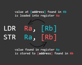
LDR R2, [R0] @ [R0] - origin address is the value found in R0. STR R2, [R1] @ [R1] - destination address is the value found in R1.
LDR functioning: loads thevalue at the address institute in R0 to the destination register R2.
STR functioning: stores the value found in R2 to the memory address found in R1.
This is how information technology would look similar in a functional assembly program:
.data /* the .data section is dynamically created and its addresses cannot be easily predicted */ var1: .word 3 /* variable 1 in memory */ var2: .word 4 /* variable 2 in memory */ .text /* start of the text (code) section */ .global _start _start: ldr r0, adr_var1 @ load the retentivity address of var1 via label adr_var1 into R0 ldr r1, adr_var2 @ load the memory address of var2 via label adr_var2 into R1 ldr r2, [r0] @ load the value (0x03) at memory address found in R0 to register R2 str r2, [r1] @ store the value found in R2 (0x03) to the memory address found in R1 bkpt adr_var1: .discussion var1 /* address to var1 stored here */ adr_var2: .discussion var2 /* accost to var2 stored here */
At the lesser we have our Literal Pool (a retentivity surface area in the same code section to store constants, strings, or offsets that others can reference in a position-independent style) where we store the memory addresses of var1 and var2 (divers in the data section at the top) using the labels adr_var1 and adr_var2. The outset LDR loads the accost of var1 into register R0. The second LDR does the same for var2 and loads it to R1. So nosotros load the value stored at the memory address found in R0 to R2, and store the value found in R2 to the retentiveness address found in R1.
When we load something into a register, the brackets ([ ]) mean: the value plant in the annals between these brackets is a retention address we desire to load something from.
When we store something to a retention location, the brackets ([ ]) mean: the value found in the register between these brackets is a memory address nosotros want to store something to.
This sounds more complicated than it actually is, so here is a visual representation of what's going on with the retention and the registers when executing the lawmaking in a higher place in a debugger:
Let's look at the same lawmaking in a debugger.
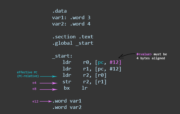
gef> disassemble _start Dump of assembler code for part _start: 0x00008074 <+0>: ldr r0, [pc, #12] ; 0x8088 <adr_var1> 0x00008078 <+4>: ldr r1, [pc, #12] ; 0x808c <adr_var2> 0x0000807c <+8>: ldr r2, [r0] 0x00008080 <+12>: str r2, [r1] 0x00008084 <+xvi>: bx lr End of assembler dump.
The labels we specified with the beginning two LDR operations changed to [pc, #12]. This is chosen PC-relative addressing. Because we used labels, the compiler calculated the location of our values specified in the Literal Pool (PC+12). You tin can either summate the location yourself using this exact approach, or y'all can utilise labels like we did previously. The only difference is that instead of using labels, you demand to count the exact position of your value in the Literal Puddle. In this case, it is iii hops (4+4+4=12) away from the effective PC position. More about PC-relative addressing later on in this affiliate.
Side annotation: In case you forgot why the constructive PC is located two instructions ahead of the current one, it is described in Function two [… During execution, PC stores the address of the current instruction plus 8 (ii ARM instructions) in ARM state, and the current instruction plus four (ii Pollex instructions) in Thumb land. This is different from x86 where PC e'er points to the next didactics to be executed…].
i.Get-go form: Immediate value equally the offset
STR Ra, [Rb, imm] LDR Ra, [Rc, imm]
Here we use an immediate (integer) equally an offset. This value is added or subtracted from the base register (R1 in the example below) to admission data at an offset known at compile fourth dimension.
.data var1: .discussion 3 var2: .word 4 .text .global _start _start: ldr r0, adr_var1 @ load the memory address of var1 via label adr_var1 into R0 ldr r1, adr_var2 @ load the retentiveness address of var2 via label adr_var2 into R1 ldr r2, [r0] @ load the value (0x03) at retention address found in R0 to register R2 str r2, [r1, #ii] @ address fashion: offset. Store the value establish in R2 (0x03) to the memory address found in R1 plus 2. Base of operations register (R1) unmodified. str r2, [r1, #iv]! @ address mode: pre-indexed. Store the value plant in R2 (0x03) to the memory accost found in R1 plus four. Base register (R1) modified: R1 = R1+four ldr r3, [r1] , #four @ address mode: post-indexed. Load the value at retentiveness accost found in R1 to register R3. Base register (R1) modified: R1 = R1+4 bkpt adr_var1: .discussion var1 adr_var2: .word var2
Let's telephone call this program ldr.s, compile it and run it in GDB to see what happens.
$ as ldr.s -o ldr.o $ ld ldr.o -o ldr $ gdb ldr
In GDB (with global environment facility) we set a break point at _start and run the program.
gef> break _start global environment facility> run ... gef> nexti iii /* to run the next 3 instructions */
The registers on my system are now filled with the post-obit values (continue in listen that these addresses might be different on your organisation):
$r0 : 0x00010098 -> 0x00000003 $r1 : 0x0001009c -> 0x00000004 $r2 : 0x00000003 $r3 : 0x00000000 $r4 : 0x00000000 $r5 : 0x00000000 $r6 : 0x00000000 $r7 : 0x00000000 $r8 : 0x00000000 $r9 : 0x00000000 $r10 : 0x00000000 $r11 : 0x00000000 $r12 : 0x00000000 $sp : 0xbefff7e0 -> 0x00000001 $lr : 0x00000000 $pc : 0x00010080 -> <_start+12> str r2, [r1] $cpsr : 0x00000010
The next instruction that will be executed a STR functioning with the starting time address way . It will store the value from R2 (0x00000003) to the memory address specified in R1 (0x0001009c) + the offset (#ii) = 0x1009e.
gef> nexti global environment facility> x/w 0x1009e 0x1009e <var2+2>: 0x3
The side by side STR operation uses the pre-indexed address mode . You can recognize this mode past the assertion mark (!). The only divergence is that the base annals will exist updated with the concluding memory accost in which the value of R2 will be stored. This ways, we store the value found in R2 (0x3) to the memory address specified in R1 (0x1009c) + the commencement (#iv) = 0x100A0, and update R1 with this exact address.
global environment facility> nexti gef> x/w 0x100A0 0x100a0: 0x3 gef> info annals r1 r1 0x100a0 65696
The last LDR operation uses the post-indexed address mode . This ways that the base of operations annals (R1) is used every bit the final address, and so updated with the showtime calculated with R1+4. In other words, it takes the value found in R1 (not R1+four), which is 0x100A0 and loads it into R3, then updates R1 to R1 (0x100A0) + first (#4) = 0x100a4.
gef> info register r1 r1 0x100a4 65700 gef> info register r3 r3 0x3 3
Here is an abstruse illustration of what's happening:
2.Outset grade: Register as the offset.
STR Ra, [Rb, Rc] LDR Ra, [Rb, Rc]
This offset form uses a register as an offset. An case usage of this showtime course is when your code wants to admission an assortment where the alphabetize is computed at run-time.
.data var1: .word 3 var2: .give-and-take 4 .text .global _start _start: ldr r0, adr_var1 @ load the retentiveness address of var1 via label adr_var1 to R0 ldr r1, adr_var2 @ load the retentiveness address of var2 via label adr_var2 to R1 ldr r2, [r0] @ load the value (0x03) at memory address found in R0 to R2 str r2, [r1, r2] @ address fashion: showtime. Store the value constitute in R2 (0x03) to the memory accost institute in R1 with the beginning R2 (0x03). Base of operations annals unmodified. str r2, [r1, r2]! @ address style: pre-indexed. Store value found in R2 (0x03) to the memory address establish in R1 with the offset R2 (0x03). Base of operations register modified: R1 = R1+R2. ldr r3, [r1], r2 @ address mode: post-indexed. Load value at retentivity address found in R1 to register R3. Then alter base register: R1 = R1+R2. bx lr adr_var1: .give-and-take var1 adr_var2: .discussion var2
Later executing the first STR operation with the offset address mode , the value of R2 (0x00000003) will be stored at memory address 0x0001009c + 0x00000003 = 0x0001009F.
gef> ten/west 0x0001009F 0x1009f <var2+3>: 0x00000003 The second STR operation with the pre-indexed accost mode volition do the same, with the departure that it volition update the base register (R1) with the calculated memory accost (R1+R2).
gef> info annals r1 r10x1009f 65695 The last LDR operation uses the post-indexed address mode and loads the value at the retention address constitute in R1 into the register R2, and so updates the base annals R1 (R1+R2 = 0x1009f + 0x3 = 0x100a2).
gef> info register r1 r1 0x100a2 65698 gef> info register r3 r30x3 iii
3.First form: Scaled annals equally the starting time
LDR Ra, [Rb, Rc, <shifter>] STR Ra, [Rb, Rc, <shifter>]
The 3rd starting time form has a scaled annals every bit the offset. In this case, Rb is the base register and Rc is an immediate commencement (or a register containing an immediate value) left/correct shifted (<shifter>) to scale the firsthand. This ways that the butt shifter is used to scale the offset. An case usage of this kickoff grade would exist for loops to iterate over an array. Here is a elementary case you tin can run in GDB:
.data var1: .word 3 var2: .word 4 .text .global _start _start: ldr r0, adr_var1 @ load the memory address of var1 via label adr_var1 to R0 ldr r1, adr_var2 @ load the retentivity accost of var2 via label adr_var2 to R1 ldr r2, [r0] @ load the value (0x03) at memory accost establish in R0 to R2 str r2, [r1, r2, LSL#2] @ address mode: showtime. Store the value found in R2 (0x03) to the retention accost constitute in R1 with the offset R2 left-shifted by 2. Base register (R1) unmodified. str r2, [r1, r2, LSL#ii]! @ address way: pre-indexed. Store the value found in R2 (0x03) to the memory address found in R1 with the starting time R2 left-shifted past 2. Base register modified: R1 = R1 + R2<<2 ldr r3, [r1], r2, LSL#2 @ address style: mail-indexed. Load value at retention address found in R1 to the register R3. So modifiy base register: R1 = R1 + R2<<2 bkpt adr_var1: .word var1 adr_var2: .word var2
The first STR functioning uses the offset address mode and stores the value found in R2 at the memory location calculated from [r1, r2, LSL#2], which means that it takes the value in R1 equally a base (in this case, R1 contains the retentiveness address of var2), and so it takes the value in R2 (0x3), and shifts it left by 2. The pic below is an effort to visualize how the memory location is calculated with [r1, r2, LSL#2].
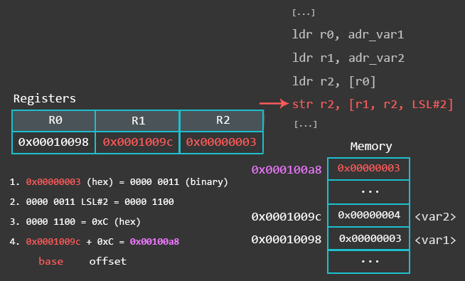
The second STR operation uses the pre-indexed address fashion . This means, information technology performs the same action every bit the previous operation, with the divergence that it updates the base register R1 with the calculated retention address later on. In other words, information technology will commencement shop the value found at the memory address R1 (0x1009c) + the offset left shifted by #ii (0x03 LSL#2 = 0xC) = 0x100a8, and update R1 with 0x100a8.
gef> info register r1 r1 0x100a8 65704 The concluding LDR functioning uses the post-indexed address mode . This means, it loads the value at the memory address found in R1 (0x100a8) into register R3, then updates the base register R1 with the value calculated with r2, LSL#2. In other words, R1 gets updated with the value R1 (0x100a8) + the outset R2 (0x3) left shifted by #2 (0xC) = 0x100b4.
global environment facility> info annals r1 r10x100b4 65716 Summary
Remember the three offset modes in LDR/STR:
- offset fashion uses an firsthand every bit offset
- ldr r3, [r1, #4]
- get-go mode uses a annals as offset
- ldr r3, [r1, r2]
- offset way uses a scaled register as offset
- ldr r3, [r1, r2, LSL#two]
How to recall the different address modes in LDR/STR:
- If there is a !, it's prefix address manner
- ldr r3, [r1, #four]!
- ldr r3, [r1, r2]!
- ldr r3, [r1, r2, LSL#2]!
- If the base register is in brackets by itself, it's postfix address mode
- ldr r3, [r1], #4
- ldr r3, [r1], r2
- ldr r3, [r1], r2, LSL#2
- Anything else is offset address mode.
- ldr r3, [r1, #4]
- ldr r3, [r1, r2]
- ldr r3, [r1, r2, LSL#2]
LDR is not just used to load data from memory into a register. Sometimes you lot will see syntax like this:
.department .text .global _start _start: ldr r0, =jump /* load the accost of the part characterization jump into R0 */ ldr r1, =0x68DB00AD /* load the value 0x68DB00AD into R1 */ jump: ldr r2, =511 /* load the value 511 into R2 */ bkpt
These instructions are technically called pseudo-instructions. We can use this syntax to reference data in the literal puddle. The literal pool is a memory area in the same section (because the literal pool is part of the code) to shop constants, strings, or offsets. In the case above we use these pseudo-instructions to reference an start to a function, and to motility a 32-chip abiding into a register in i instruction. The reason why we sometimes need to use this syntax to motion a 32-bit constant into a register in one didactics is because ARM tin can simply load a viii-scrap value in ane become. What? To understand why, yous need to know how firsthand values are being handled on ARM.
Loading immediate values in a register on ARM is not as straightforward as it is on x86. At that place are restrictions on which firsthand values y'all can use. What these restrictions are and how to deal with them isn't the most exciting part of ARM assembly, but bear with me, this is only for your understanding and there are tricks you tin can utilize to featherbed these restrictions (hint: LDR).
We know that each ARM educational activity is 32bit long, and all instructions are conditional. In that location are 16 condition codes which we can use and 1 status lawmaking takes upward four $.25 of the instruction. Then we need 2 bits for the destination register. 2 $.25 for the first operand annals, and 1 bit for the gear up-status flag, plus an assorted number of bits for other matters like the bodily opcodes. The bespeak here is, that afterward assigning bits to instruction-type, registers, and other fields, in that location are only 12 bits left for immediate values, which will only allow for 4096 different values.
This ways that the ARM instruction is only able to use a limited range of firsthand values with MOV directly. If a number can't be used directly, information technology must be carve up into parts and pieced together from multiple smaller numbers.
Merely there is more. Instead of taking the 12 bits for a unmarried integer, those 12 bits are divide into an 8bit number (due north) being able to load whatever 8-bit value in the range of 0-255, and a 4bit rotation field (r) being a correct rotate in steps of 2 betwixt 0 and thirty. This means that the full firsthand value v is given by the formula: v = n ror ii*r. In other words, the simply valid firsthand values are rotated bytes (values that can be reduced to a byte rotated by an even number).
Here are some examples of valid and invalid immediate values:
Valid values: #256 // 1 ror 24 --> 256 #384 // 6 ror 26 --> 384 #484 // 121 ror 30 --> 484 #16384 // 1 ror 18 --> 16384 #2030043136 // 121 ror viii --> 2030043136 #0x06000000 // six ror 8 --> 100663296 (0x06000000 in hex) Invalid values: #370 // 185 ror 31 --> 31 is not in range (0 – xxx) #511 // 1 1111 1111 --> flake-pattern tin't fit into one byte #0x06010000 // 1 1000 0001.. --> bit-pattern can't fit into one byte
This has the consequence that it is not possible to load a total 32bit address in one go. We can bypass this restrictions by using one of the following two options:
- Construct a larger value out of smaller parts
- Instead of using MOV r0, #511
- Split 511 into two parts: MOV r0, #256, and Add together r0, #255
- Use a load construct 'ldr r1,=value' which the assembler will happily convert into a MOV, or a PC-relative load if that is not possible.
- LDR r1, =511
If you endeavor to load an invalid immediate value the assembler will mutter and output an error saying: Fault: invalid constant. If you encounter this error, you now know what information technology means and what to do nearly information technology.
Allow'south say yous desire to load #511 into R0.
.section .text .global _start _start: mov r0, #511 bkpt
If yous try to assemble this code, the assembler will throw an error:
azeria@labs:~$ as test.s -o test.o examination.s: Assembler messages: examination.s:5: Error: invalid abiding (1ff) afterward fixup
You lot demand to either split 511 in multiple parts or you lot use LDR as I described earlier.
.section .text .global _start _start: mov r0, #256 /* 1 ror 24 = 256, then it'southward valid */ add r0, #255 /* 255 ror 0 = 255, valid. r0 = 256 + 255 = 511 */ ldr r1, =511 /* load 511 from the literal pool using LDR */ bkpt
If yous need to figure out if a sure number can exist used every bit a valid immediate value, y'all don't need to summate information technology yourself. Y'all tin utilise my little python script called rotator.py which takes your number as an input and tells you if it can be used equally a valid immediate number.
azeria@labs:~$ python rotator.py Enter the value you want to cheque: 511 Sorry, 511 cannot be used as an immediate number and has to be split. azeria@labs:~$ python rotator.py Enter the value you want to cheque: 256 The number 256 tin can be used as a valid immediate number. 1 ror 24 --> 256

Source: https://azeria-labs.com/memory-instructions-load-and-store-part-4/
Posted by: mendezloomely.blogspot.com
0 Response to "How To Many Bits Doe Registers Hold In Armsim"
Post a Comment